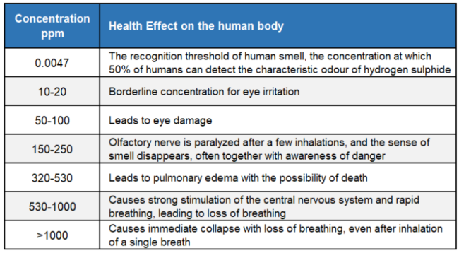
Have you ever wondered why hydrogen sulphide (H2S) is so feared by pressure vessel and piping inspectors? Of course, anyone who works in the oil and gas industry understands the personal danger of H2S. One whiff can kill you. Table 1 presents the health effects of H2S concentrations on the human body according to the UK Health & Safety Executive.
Table 1. H2S concentration health effect on the human body
Without going into the dangers to affected personnel and rescuers, we will now concentrate on the process safety dangers.
In 2006 I was running a Risk Based Inspection (RBI) workshop in Kuwait with 17 participants. In the early afternoon someone’s phone rang, then another, then another. Within ten minutes I was left alone with only two of the participants – because they had switched their phones off. We soon found out that there had been an explosion at an unmanned gathering station in the field. A contractor had a job at the station and the lead hand had been given the key. On reaching the station the lead hand exited the crew cab pickup leaving the other three contractors in the truck. He then unlocked the gate and stepped through, opening the gate. He waved the pickup through to enter the station and as it did, the truck ignited a gas cloud. The three contractors inside the truck were not badly hurt but the lead hand suffered 80% burns and died in hospital three days later. The investigation found a crack near a weld on the main gas line exporting from the station. The cause was hydrogen charging.
But what is hydrogen charging?
As the name suggests hydrogen charging is the process of hydrogen working its way through the steel wall of the pipe of pressure vessel. Let’s discuss where the hydrogen comes from.
Imagine a pipe transporting crude oil. Our crude has some hydrogen sulphide (H2S) and crude oil always has some water content unless the water has been completely removed in a separation / drying process. Some of the H2S and the water will naturally react.
(1) The sulphuric (and sulphurous) acid will react with the iron of the steel wall.
(2) At the same time the H2S also reacts with the iron of the steel wall.
(3) In each case, we have free hydrogen released into the crude oil stream. This is not a huge amount of hydrogen but even if it were we could keep this in the stream as it contributes to the calorific value. However, the Iron Sulphide (FeS) now acts as a catalyst to break the molecular hydrogen (H2) into atomic hydrogen. This is where things get interesting.
A molecule of hydrogen is made up of two protons each with its own electron and the complete molecule has a diameter of about (depends where you get the information from) 274 picometres (pm).
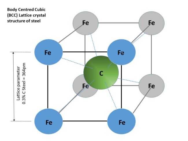
Figure 1. Body Centered Cubic (BCC) lattice crystal structure of steel [API 571 section 5.1.2.3]
The lattice parameter of 0.3% carbon steel is about 364 pm. As you can see in Figure 1 the molecular hydrogen is just too big to get through the gaps between the iron atoms. But remember the catalytic effect of the FeS on the molecular hydrogen – it causes the hydrogen to crack into two atoms. Notionally the atoms are also too big to get through the gaps but the BCC crystals of steel have many gaps (defects and vacancies) so it is possible for the hydrogen atoms to gradually work their way through the steel but it takes a long, long time for the hydrogen to work its way to the outside. The atomic hydrogen will occasionally lose its electron and becomes an ion of hydrogen – which is effectively a proton. The protons are much smaller than the atoms so are free to move through the steel very easily.
As shown in Figure 2, once the atomic or ionic hydrogen reaches a cavity in the steel lattice, such as a piece of dirt caught during manufacture, the ionic hydrogen can capture a free electron forming atomic hydrogen and the atomic hydrogen can combine to form molecular hydrogen. And the molecular hydrogen is now trapped.
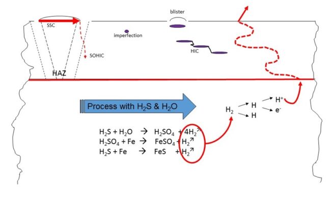
Figure 2. The catalytic effect of the FeS on the molecular hydrogen – production of hydrogen atom and consequences [API 571 section 5.1.2.3]
Over months and years, more and more hydrogen becomes trapped in the space such that the hydrogen acquires a pressure. As the hydrogen pressure builds it results in stresses in the steel that are greater than the yield or even tensile strength of the steel causing a local failure. That failure can take several forms (Figure 3).
1. If the steel is ductile the high stresses will cause a tear or lamination that is usually parallel to the wall surface. The lamination now has a greater surface area so more hydrogen enters and the pressure continues to rise.
► If several laminations occur near to each other the stresses at the lamination tips cause cracks which tend to join lamination ends together – even at different steel depths. This is known as HIC (hydrogen induced cracking) or stepwise cracking.
► If the lamination occurs near the surface of the steel the smaller thickness yields more readily than the thicker portion and we end up with a blister rising from the steel surface.
2. If the steel is not ductile, such as in the Heat Affected Zone (HAZ) of a weld or perhaps a high strength steel or even an older steel that is simply not tough enough, then the high stresses cause cracks instead of plastic deformation.
► Stress Oriented Hydrogen Induced Cracking (SOHIC) is similar to HIC but appears as arrays of cracks stacked on top of each other resulting in a through-thickness crack that is perpendicular to the surface and is driven by high levels of stress (residual or applied). They usually appear in the base metal adjacent to the HAZ where they initiate from HIC damage or other cracks or defects including sulphide stress cracks
► Sulphide Stress Cracking (SSC) can initiate on the surface of steels in areas of high hardness in the weld metal and HAZ. Zones of high hardness can sometimes be found in weld cover passes and attachment welds which are not tempered (softened) by subsequent passes. PWHT (post weld heat treat) is beneficial in reducing the hardness and residual stresses that render steel susceptible to SSC.
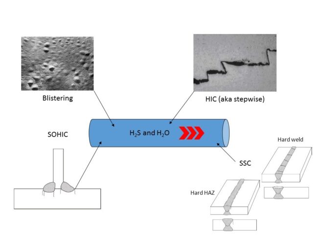
Figure 3. Potential failure forms due to H2S hydrogen charging [API 571 section 5.1.2.3]
So, what can we do to avoid these problems?
► NACE (National Association of Corrosion Engineers) has produced an international standard (MR 0175/ ISO 15156-1) that guides us in appropriate material selection. This standard was first introduced in the 1960’s but the defective pipe I described in Kuwait was installed in the 1950s so the steel was not clean enough and had many initiation locations (aka dirt in the steel) and was harder than we would accept now.
► If the partial pressure of the H2S is more than 0.3kPa (0.05 psi) then MR 0175 shall apply. This also states that the weld procedure for all welds for sour service SHALL include a hardness test (for detail go to clause 7.3.3.2 of ANSI/NACE MR0175/ISO 15156-2:2009(E).
► Blisters may be carefully vented to halt the build-up of molecular hydrogen so the pressure is relieved. Check out API 579-1/ASME FFS-1 (2007) part 7 for a simple guide on how to qualify a blister for continued service.
► Take regular samples of free water to monitor any changes in process conditions that may cause hydrogen charging.
► During inspections pay special attention to weld seams and nozzles. NACE RP0296 has some recommendations that are very useful.
► Use Wet Fluorescent Magnetic Testing (WFMT), Eddy Current (EC), X-ray or gamma ray (RT) or Alternating Current Field Measurement (ACFM) to check for cracks and laminations. Ultrasonic techniques (UT) can also be used and short wave UT is especially useful for volumetric inspection and crack sizing. Acoustic emission can be used to monitor crack growth.
► All of these standards are extremely useful but always remember that your local jurisdiction takes priority in case of a conflict.
I hope you find this series of posts useful. To learn more about similar cases and how to minimize operational troubles, I suggest attending our ME41 (Piping Systems – Mechanical Design and Specification) and ME43 (Mechanical Specification of Pressure Vessels and Heat Exchangers) courses.
Stay Safe.
By: Ron Frend, Head of Facilities Training
