Specification breaks or “Spec Breaks” are extremely important, and are not normally taught in college. They are noted on Piping and Instrumentation Diagrams (P&ID’s) and indicate where a specification change has occurred on piping with regards to Flange Rating, Material, or insulation. They are extremely important in Hazard and Operability Reviews (HAZOP’s) when reviewing relief valve settings and the hazards introduced by creating overpressure situations by opening and closing valves downstream from a high pressure source.
SAFETY MOMENT:
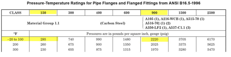
You are working in a gas plant and an upset condition occurs. It’s 3 AM and cold. The flare is going off, alarms are sounding, lights are flashing, and your adrenaline is pumping. The operators correct the situation, and the system returns back to normal. However; a relief valve (Figure 1) on a high pressure ANSI 900#sSeparator failed to reseat and is leaking a lot of gas to flare. You’re asked to line-up the stand-by relief valve, and then isolate the leaking valve so that it can be sent in for repairs. Table 1 presents the portion of ANSI class rating.
Table 1 – Flange Pressure, Temperature Rating
Question: Do you close VALVE #1 or VALVE #2 first, or does it matter?
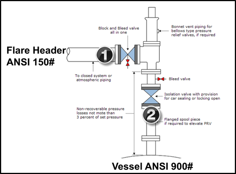
Figure 1. Relief Valve Block Closing Sequence
Answer: As seen in Figure 2, you should close VALVE #2 first. It isolates the high pressure gas from the relief valve. What many people do not know is that the relief valve has a spec break across the valve. The downstream flanges are only rated for 150#. If you mistakenly closed Valve #1 a loss of containment would probably have occurred with serious injury. In a recent class, approximately 50% of students answered this question incorrectly. This design exists all over our hydrocarbon industry.
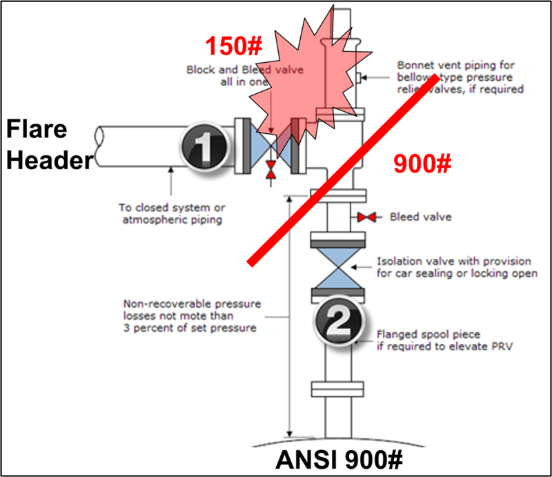
Figure 2. Valve Closing Sequence Answer
Can your operators and engineers answer this question correctly? It may be a great topic for your next safety moment/tailgate safety meeting.
Another source to review is API 14C [1]. Spec breaks are highlighted in Figure 3. (API 5000 to ANSI 600#; and ANSI 600# to ANSI 150#). One example is discussed below:
The well flows into the system at 5,000 psi and its pressure is reduced by a fixed choke. The vessel is operated at 1,000 psi and is protected by a relief valve set at 1200 psi. The vessel has a manual drain valve #5 that is closed. The level is maintained by a level control valve and a bypass exists around the separator for maintenance.
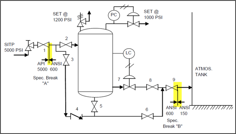
Figure 3. Specification Breaks Example: What’s Wrong?
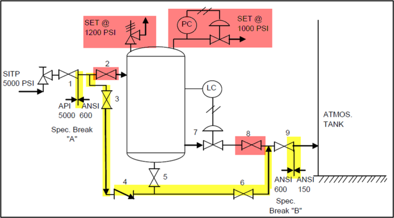
Figure 4. Spec Break Error
In Figure 4 if you close red highlighted valves 2 and 8 then the yellow highlighted piping system is isolated from the relief valve and is currently unprotected from overpressure from the well with a shut-in tubing pressure of 5,000 psi if either of the following valves are closed #3, #6, #9, or the check valve 4 is plugged. If any of these valves are closed the high pressure source will equalize across the choke causing a loss of containment in the downstream piping which is blocked from the relief valve.
If Valve #2 and Valve #8 are closed, and the others are open, then the atmospheric tank will be catastrophically destroyed.
In order to find “spec break busts” and design errors, start at the highest pressure source and then open and close downstream valves to check that each piping component is protected by a relief valve.
For example, by performing simulation, start with the shut-in tubing pressure of 5,000 psi. Close the next downstream valve which is the choke. The upstream piping and closed choke must be rated to 5,000 psi. There is no issue since the spec break is the downstream flange of valve 1. All piping and components upstream of this break are rated to API 5,000. Next open the choke, open valve 1, close valve 2 and valve 3. The piping segment is not protected by a relief valve and is only rated to an ANSI 600 # system. This piping segment will fail and cause a lack of containment. A solution would be to eliminate valve 2 or provide a PSV upstream of valve 2.
To learn more about similar cases and how to minimize operational problems, we suggest attending ourPS4 (Process Safety Engineering), G4 (Gas Conditioning and Processing), G5 (Advanced Applications in Gas Processing, PF3 (Concept Selection and Specification of Production Facilities in Field Development Projects) and PF49 (Troubleshooting Oil & Gas Processing Facilities) courses.
PetroSkills | John M. Campbell offers consulting expertise on this subject and many others. For more information about these services, visit our website at http://petroskills.com/consulting, or email us at consulting@PetroSkills.com.
By: James F Langer, P.E.
References
- API 14C, Recommended Practice for the Analysis, Design, Installation, and Testing of Basic Safety Systems for Offshore Platforms, 30 CFR 250.1628(c), American Petroleum Institute, 2001
