Piping vibration is a major cause of concern in process plants, particularly in the oil and gas industry where the loss of containment could be catastrophic. This Tip of the Month explains the root causes of piping vibration, natural frequencies and how they may be changed using appropriate structural supports and layouts.
Imagine sitting in your office having a well-earned cup of coffee. The phone rings and on the other end is an irate production supervisor screaming that the plant is about to explode because the new section of pipe you installed last week is galloping up and down. Vast amounts of natural gas will be released into the plant when the pipe breaks. You calm him down and arrange to quickly take the section of pipe out of service. Now that everything is safe, you must figure out what went wrong. We are embarking on a voyage of discovery, that entails us calling at the following way stations:
PART 1 – Calculate the natural frequency of a pipe
PART 2 – Calculate VIV (Vortex Induced Vibration) affecting the pipe
PART 3 – Calculate the effect of flow induced vibration as flow rates change
PART 4 – Determine the severity of the vibration: Is it acceptable or does it need modifications?
PART 1: NATURAL FREQUENCY OF A PIPE
Why do pipes gallop?
Maybe galloping isn’t the right word; I would prefer to say the pipe is vibrating. But why is it vibrating so much? One word – resonance.
If you seat a child on a swing and you give a gentle nudge to the swing every time the child swings back towards you, you will quickly be able to get the swing higher and higher. You only need a very small force because you waited until the swing had reached its limit of movement (the limit of the swing) and only then did you give that gentle push. But you did it EVERY time the swing moved back towards you. A couple of interesting things are happening here.
1. You are pushing at exactly the same frequency as the frequency at which the child is swinging. Don’t forget that if you are troubleshooting a pipe vibration problem the natural frequency will depend not only on the steel of the pipe but also the mass of the fluid inside.
2. You are pushing at the same position in the swing cycle – in other words you have “locked phase” with the swing.
The occurrence of these two “interesting” points means you are in RESONANCE with the swing. When a pipe is vibrating heavily it is almost always because there is a resonance issue. The swing has a natural frequency because it has a period of oscillation that depends on the mass of the swing and the length of the pendulum. This is the reason why a pendulum is used on a clock. If you can work out the period of the cycle back and forth, then you know the frequency.
If the time period of oscillation is one second, then the frequency is one per second or 1Hz. If the time period is half a second, then the frequency is 2Hz and so on. By the same reasoning the pipe has a natural period of oscillation and so it has a natural frequency. The natural frequency of the pipe depends on its stiffness and its mass; the stiffer the pipe the higher the frequency, the more mass the pipe (including contents) has, the lower the natural frequency.
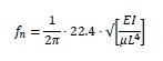
To calculate the natural frequency of a pipe with rigid supports use the following formula:
Where:
fn = natural frequency of the pipe (Hz)
E = Young’s modulus of elasticity (200 GPa or 30E6 psi for steel – approximately but close enough)
I = 4th polar moment of inertia for the pipe (0.049*[OD4-ID4]) in inches or metres
µ = mass per unit length of the pipe (remember to include the mass of the fluid) lbs/inch or kg/m
L = distance between pipe supports (inches or metres)
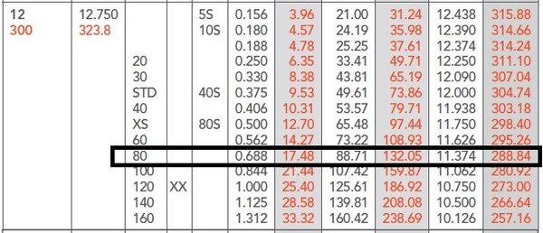
Let’s find the natural frequency of a 12” (300 mm) pipe made of A-106 GrB schedule 80 that is first empty and then filled with water. I’ll use SI units to make the math easier. Pipe supports are 5 m apart.
Given:
Pipe OD = 323.8 mm
Pipe ID = 288.84 mm
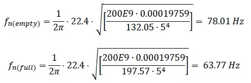
Mass/length empty = 132.05 kg/m
Mass/length full = 132.05 + π (0.28884)2/4 * 1000 = 197.57 kg/m
E = 200 x 109 Pa
Calculate I:

Natural Frequency:
Now you know the natural frequency of the pipe you ask your vibration techs to take a vibration measurement on the pipe when it’s in operation. If the frequency is the same as your calculated frequency, then the pipe has a resonance problem and the next step is to identify what is the force that is exciting the natural frequency.
PART 2 – CALCULATE VIV (VORTEX INDUCED VIBRATION)
In part 1 we determined the natural frequency of the pipe so now we know the pipe natural frequency, but you are not standing there pushing it – so what is? It could be any of a number of things:
►Vibration at the same frequency coming from a pump or compressor (usually speed related). This could be caused by unbalance, misalignment, something may have come loose or just about any fault on a machine that causes a vibration at the same frequency as the natural frequency.
►Flow induced vibration. Now, this could be from the internal flow of the fluid through the pipe or even from wind flowing across the outside of the pipe. We have all seen the effect of wind induced vibration on street lamps or poles so when the wind hits a particular speed the pole starts to sway. That’s because the oscillation force associated with the wind is a function of the pipe outside diameter and the wind speed so the wind vortexes or swirls on the downwind side of the pipe and the vortexing induces KARMAN vibration.
Check this out for more information.
I usually start with the easiest option. Have a look around the pipe and see if there is any rotating equipment that has a run speed (or a harmonic of run speed) that is very close to the pipe natural frequency. If there is can either change the speed of the machine (if possible, because that is the easiest option) or change the natural frequency of the pipe. An easy way to change the natural frequency of the pipe is change the value of L – in other words change the location of the pipe supports or maybe just add another support. If you add another support be careful that you put it at a location of high amplitude – in other words an antinode of vibration.
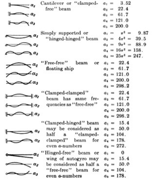
You can see from the following image that the modifier we used (a=22.4) is only applicable to the first mode of vibration of a “clamped-clamped” beam or pipe. If you install another pipe support halfway between existing supports but the pipe is vibrating at the second mode (a=61.7) the amplitude of vibration will be unaffected. I usually hammer in a stout piece of wood as a (very) temporary measure to see if that indeed reduces the vibration.
If you find that there is no rotating equipment nearby that could affect your pipe we could see if there are any other possible causes and an easy one to check is vortex induced vibration.
For the same reason that a flag flutters, a pipe (or any object) will experience an oscillatory force when placed in a fluid flow. As the wind flows across the pipe there are tiny differences in air pressure from one external side of the pipe to the other, so the wind finds slightly less resistance on one side and more wind flows towards the lower pressure. As more wind flows towards the lower pressure side that side experiences an increase in air pressure so the flow of wind flips over to the other side. The other side experiences the increase in air pressure so the flow flops back again. The flow of wind is now flip flopping back and forth causing a transverse oscillating force on the pipe.
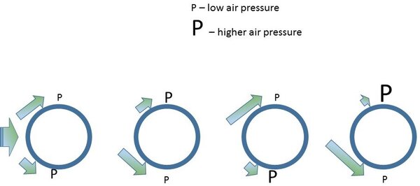

By Cesareo de La Rosa Siqueira – http://www.mcef.ep.usp.br/staff/jmeneg/cesareo/vort2.gif, Copyrighted free use
Going back to our flag analogy, the pipe flutters as the wind passes the flagpole and vortexes on the downwind side. The vortex is traveling along the flag and the flag “flutters.”
We, though, are interested in what is happening to our pipe. According to Strouhal and Karman there is a distinct relationship between the speed of the wind, the diameter of the pipe and the frequency of the oscillating force.
St = fD / V
Where:
f is the frequency (Hz)
D is the diameter of the pipe
V is the wind velocity.
St is the Strouhal number. This does vary somewhat with Reynolds number, but we can assume it to be 0.22.
So, if we have a wind velocity of 10 m/s and we know that our pipe has an OD of 0.3238 m (see Part 1 where we calculated natural frequency) the VIV frequency is 0.22*10/0.3238 = 6.79 Hz. Easy isn’t it?
However, the vortexing frequency effect is not limited to external wind. You will get the same effect from fluid flowing inside the pipe as it flows across an obstruction. So if we have a gate valve with a non-rising stem with a stem diameter of 3.5 cm and a fluid flow of 10 m/s we would have a vortexing frequency of 62.8 Hz. Remember that our pipe has a natural frequency of 63.77 Hz which is close enough to ensure resonance.
In our next article, we will examine the effect of changing the fluid velocity and see how that affects resonance in our pipe.
PART 3 – VIBRATION FROM FLOW VELOCITY
In Part 1 we figured out the natural frequency of a pipe and in Part 2 we looked to see if the resonance excitation was from a nearby rotating equipment or perhaps vortex induced vibration. If neither of these options came close to identifying the forcing frequency, we need to look at slightly more exotic causes.
Most people who work in process, power, oil & gas or refining will have come across a problem in which a perfectly normal section of piping with no significant vibration “suddenly” starts to vibrate for no apparent cause apart from a slight change in flow rate. But that doesn’t seem to make any sense. We have made no change to the mass or stiffness of the pipe, so the natural frequency hasn’t changed. We have not changed any run speed of nearby equipment and even if we check VIV vibration it doesn’t even come close to the problem frequency. What the heck could it be?
Let’s take a trip down to the train station. The express through train is coming down the track and as it passes us, we hear a definite change in pitch. A high pitch as the train travels towards us and a lower pitch as the train moves further away. We are talking about the DOPPLER effect.
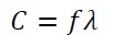
To understand Doppler, we need a good understanding of noise and sound. When we speak the sound, we make travels through the air at about 330 m/s. That doesn’t mean we are expelling air from our mouth at that speed – that would be rather unpleasant. As our voicebox vibrates it creates an area of high air density as it pushes onto the air molecules. That high-density rams into the air next to it and bounces back transmitting the energy to the adjacent air molecules. The rate at which the energy is transmitted to adjacent air molecules is the speed of the sound. Remember from high school physics class that the speed of sound is function of frequency and wavelength?
Where:
C is the speed of sound in the fluid
f is the frequency of the sound
λ is the wavelength between the high-pressure pulsations of the sound
As a stationary observer of a stationary object that is making a noise the speed of sound is set by the air density and the air pressure. The pitch or frequency is determined by the distance between the high-pressure pulsations. So, let’s see what happens if we start moving the object making the noise.
When our train is stationary the sound moves away from the train at 330 m/s in all directions. The wavelength is the same as the same travels in all directions. When the train starts to move, we have the sound AND the train traveling in the same direction to the front of the train but moving in OPPOSITE directions when viewed from behind the train. The speed of the sound hasn’t changed but because the train and the sound are traveling in the same direction at the front of the train the wavelength is compressed. Using C = fλ as the wavelength is compressed and the speed of sound stays the same then frequency must increase. The opposite effect happens as the train moves away from us, so we hear a lower frequency or deeper tone.
Factor C is a physical value depending on the properties of the fluid. However, the wavelength is affected by the speed of the fluid flow through the pipe – the Doppler effect.
But we have a pipe with fluid traveling along the inside of the pipe. What does this have to do with moving trains? Only that in both cases we have to think about Doppler.
Let’s move to wind musical instruments. When air is blown into a trumpet or trombone you only get a distinct tone if you blow into the mouthpiece at a particular rate – that is why trumpeters “purse” their lips to get the right airspeed. When you get the correct airspeed the wavelength becomes the same as the length of tubing, so you get a standing wave and the instrument sounds the desired note. The length of the tubing can be adjusted on a trumpet using valves or on a trombone using the slide. In effect, you are changing the wavelength of the air and that is changing the frequency. All of us have tried blowing across a part empty bottle and we get a tone if the speed of the blow is “just right.”
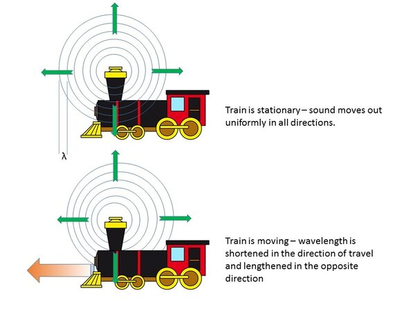
The nearest our pipe is to the analogy of a trumpet is a section of pipe between two bends. The half wavelength is actually longer than the distance between the bends (add about 15%). The part open bottle analogy equates to a dead leg at a tee and in that case, we have a quarter wavelength.
So now let’s combine the standing wave and the Doppler effect in our pipe. Instead of a train moving we now have liquid or gas moving along the pipe. In effect, we are causing the wavelength to change by changing the flow velocity relative to the speed of sound. This can get us into trouble in one of two ways:
1. If you have a forcing vibration at the same frequency you get resonance of the fluid inside the pipe. This happened to me once on a pump running at 2970 rpm discharging into a line that had a length between the discharge flange and the next tee that equated to the standing wave that had a frequency of 50 Hz. Vibration at about 20 mm/s rms and a bearing life of 3 months. We changed the configuration of the discharge piping and vibration came down to less than 2 mm/s and no more bearing failures.
2. If the frequency of the standing wave is close to the natural frequency of the mechanical section of pipe you have resonance. This happened on the discharge of a large blower in China. The distance between the discharge flange of the blower and the NRV gave a standing wave with a frequency that was very close to the natural frequency of the piping. We moved the NRV and the vibration problem disappeared.
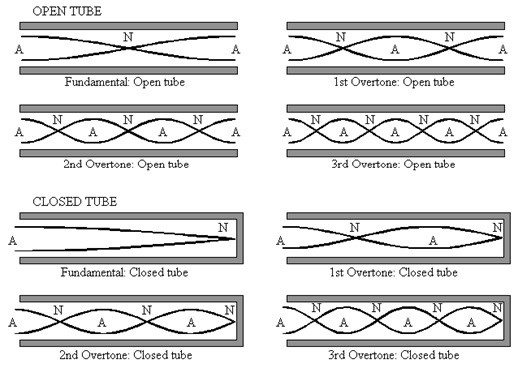
Remember that standing waves can occur not only at fundamental frequency but also at “overtones”. Don’t ignore the overtones.
We still use C = fλ to calculate the fundamental frequency so with a speed of sound of 330 m/s and an end-corrected wavelength of 10 m we would have a fundamental tone of 33 Hz. But as soon as fluid flows through the pipe we have to modify that wavelength. So, if we flow at 33 m/s that means a 10% change in apparent speed of sound so we would get a new frequency of (330+33)/10 = 36.3 Hz.
Our pipe is carrying 22 MW natural gas at 80 ֯C with a speed of sound of 365 m/s. Our section of piping has a length of 8.5 m between bends which equates to an open/open pipe of 8.5 m length. which gives a wavelength of 17 m. Add 15% to that length for “end effect” correction and we get a fundamental tone or frequency of 365/ (10*1.15) = 18.54 Hz.
But we now flow gas through the pipe at 20 m/s which, when considering the Doppler effect, changes that frequency to 19.72 Hz. But what makes it really worrying is that the first overtone is 39.45 Hz, the second overtone is 49.31 Hz but the 3rd overtone is 78.9 Hz which is rather close to our mechanical natural frequency of 78 Hz.
On very large diameter piping there is a possibility of shell wall resonance but that is quite rare and tends to happen on trunking rather than pipework (large diameter and thin wall) so we won’t get into it here.
PART 4 – LIMITS FOR PIPING VIBRATION
Okay – let’s recap. We have a pipe with a natural frequency and a force with the same frequency. This means high amplitude vibration. So what?
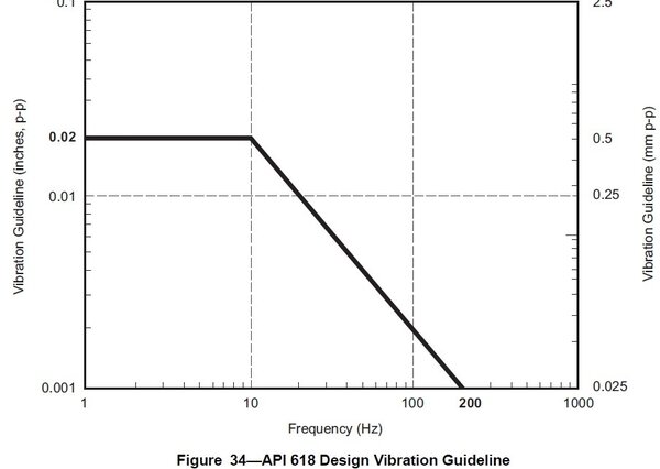
If we leave a vibrating pipe in place long enough and the vibration is severe enough the pipe will develop a crack and we get a leak. We are talking about fatigue failure. To make things easy for us there are several versions of fatigue limits we can apply to piping and the one I will mention is API STD 618. Now before you start jumping up and down complaining that is a standard for reciprocating compressors let me say that yes, you are right. But this section of the standard works for all steel piping because it is VERY conservative.
Let’s look at some of the detail.
Section 7.9.4.2.5.2.4 Piping Design Vibration Criteria
The predicted piping vibration magnitude shall be limited to the following:
► A constant allowable vibration amplitude of 0.5 mm peak-to-peak (20 mils peak-to-peak) for frequencies below 10 Hz (the frequency of 10 Hz is also according to ISO 10816).
► A constant allowable vibration velocity of approximately 32 mm/s peak-to-peak (1.25 in./s peak-to-peak) for frequencies between 10 and 200 Hz.
• We need to be aware that 32 mm/s pk-pk is the same as 16 mm/s peak and 11.3 mm/s rms. To convert displacement to velocity:
• V = 2π. Displacement. Frequency
• So 0.5 mm at 10 Hz gives a velocity of 2π*0.5*10 = 31.42 mm/s
• Vibration measurements are almost always displayed in terms of peak-peak for displacement (total movement) but velocity readings are only ever shown as zero to peak or even rms so don’t be confused by the API 618 limits. To see the relationship between pk-pk, peak and rms look at the image below.
The rms. or root mean square velocity is a quantitative measure of the effective velocity and reflects the power or energy being used to vibrate the machine mass. Peak value is the maximum amplitude seen during the measurement referenced to zero velocity and peak to peak is a measure of the total movement so is usually only used for displacement.
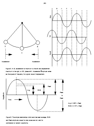
This image illustrates the movement of a pendulum. The figure above shows that at position B and C, the velocity is zero, and at position A the velocity is maximum, first to the right, then to the left. The negative peak velocity differs only in direction, not magnitude. The rate of change of displacement is the velocity, therefore if D is expressed in terms of mm, instead of the usual micron, then the product 2pfD will be the velocity in mm/s which are the units used for velocity in vibration work.
This relationship between velocity and displacement is an important factor when considering severity of piping vibration – if you want to be accurate. I really don’t care about vibration amplitudes or movement in pipes, what I care about is the stresses that have been imparted to the pipe. If we consider a resonant pipe, then the actual forces are quite low but the physical movement (or displacement) could be quite high.
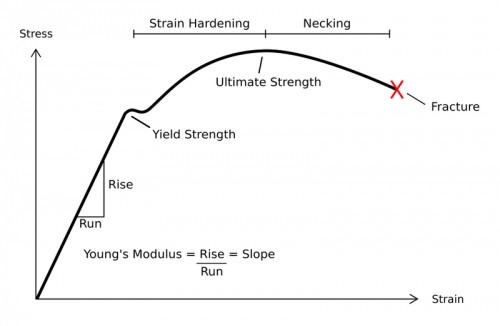
If we consider the stress-strain diagram for carbon steel, A106GrB has a tensile stress specified at 415 MPa and

We need to make sure the stress value due to the bending effect of the piping vibration is well below the yield value and we can use our high school physics knowledge to do this.
Stress from bending = 8EDΔ/L^2
Where:
E = Youngs modulus
D = pipe outside diameter
Δ = peak to peak displacement
L = length of pipe between supports
So, let’s say our 5 m pipe has a maximum vibration amplitude of 0.5 mm pk-pk. The bending stress is
S = 8 * 200E9 Pa * 0.3238 m * 0.5 / 52 = 10.36 MPa
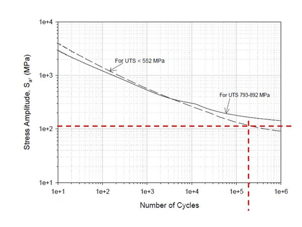
That sounds quite reasonable but what happens if the vibration is 5 mm pk-pk? The stress is now 103 MPa. Compare that to our yield stress of 240 MPa and you would think our pipe should be fine, but API 618 warns us that if there is a cyclic stress level in the piping that stress level must not exceed the endurance limits of the piping materials. So, what is the endurance level? It is the value of the stress below which a material can presumably endure an infinite number of stress cycles, that is, the stress at which the S-N diagram becomes and appears to remain horizontal. The existence of a fatigue limit is typical for carbon and low alloy steels.
Looking at the image below we have a plot of applied stress against the number of cycles the metal endured before rupturing of a carbon steel of a known UTS. It is possible to predict (very approximately) the life to failure of the equipment if we have this plot. Our A-106 pipe steel follows the dashed line fairly closely so we can see that if we have a stress of 103 MPa the steel would be expected to fail due to cyclic loading at about 200,000 cycles.
If our pipe is vibrating at 67 Hz that means 67 cycles per second, so we have a life before failure of 200,000 / 67 = 2958 seconds – less than an hour.
To operate our pipe safely for an extended period then the vibration MUST induce a stress that is less than the endurance limit. And that is why the API recommendation is so conservative. But if you really need to operate the equipment you can carry out a fatigue analysis as we have done or you could use API 579-1/ASME FFS-1 which can guide you through a step by step procedure to determine if you can use the pipe for an extended time.
In conclusion, if your pipe is vibrating, you should do the following:
►Find out if the vibration is resonant – that means find the natural frequency
►If the vibration is resonant find out what is the forcing frequency – that could be a nearby piece of equipment, external effects such as wind or fluid flow induced vibration
►Determine if the vibration levels are acceptable – you could use API 618 for that or carry out a full fatigue analysis.
To remedy the problem, you simply have to separate the natural frequency from the forcing frequency.
To change the natural frequency, you must change either the stiffness or the mass. It is usually much easier to change the effective mass by changing the length between supports either by moving one of the existing supports or by adding a new one.
Otherwise, you have to attack the forcing frequency. If it’s a rotating machine you can change the speed, isolate the machine from the pipework or fix the vibration issue such as unbalance or misalignment. If the problem is flow induced or VIV you will have to do the analysis to positively identify the culprit and make changes in flow rate, piping arrangement or even production procedures.
I hope you find this series of posts useful. To learn more about similar cases and how to minimize operational troubles, we suggest attending our ME41 (Piping Systems – Mechanical Design and Specification) and PF49 (Troubleshooting Oil and Gas Processing Facilities) courses.
By: Ron Frend, Head of Facilities Training
