Compression refrigeration is the most common mechanical refrigeration process. It has a wide range of applications in the gas processing industry, including [1]:
►Chilling natural gas for hydrocarbon dewpoint control
►Chilling natural gas for NGL extraction
►Condensation of reflux in deethanizers
►NGL product storage and transportation
►Natural gas liquefaction (LNG)
Continuing the March 2020 [2] and June 2019 [3] Tips of The Month (TOTM), this tip reviews several options for reducing the compression power requirement for a mechanical refrigeration plant with mono ethylene glycol (MEG) injection for hydrocarbon dewpoint (HCDP) control. Specifically, for each option the calculated required compression power is compared with the base case and percentage reduction reported. All of calculations are performed using GCAP software [4].
Figure 1 presents the process flow diagram for a simple propane refrigeration unit. The mixture of refrigerant vapor and liquid enters the chiller/evaporator typically 3-6°C (5-10°F) lower than the temperature to which the process stream is to be cooled. The refrigerant leaves the condenser as a saturated liquid or slightly subcooled. For air cooling, the condenser temperature will usually be 14-16°C (25-30°F) above the air dry bulb temperature. For water cooling the condensing temperature will be 5-10°C (9-18°F) above the water temperature. Refer to reference [1] for more detail.
The listed process conditions in Figure 1 are for the base case study. The specified values are shown in red color and the calculated values are shown in black color.
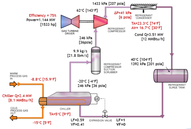
Figure 1. Example of process flow diagram for a simple propane refrigeration system
Figure 2 presents the process flow diagrams for a typical HCDP control plant using mechanical refrigeration with MEG injection system. The details of a mechanical refrigeration are given in Chapters 6 and 15 of the Gas Conditioning and Processing, Volumes 1 and 2 [1, 5].
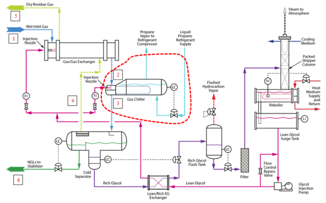
Figure 2. Typical mechanical refrigeration plant with MEG Injection system for rich wet inlet gas [5]
Case Study:
Let’s consider a rich wet inlet gas (Stream 1 in Fig. 2) at 7500 kPa (1088 psia) and 12 °C (54 °F) with known compositions and a flow rate of 8.08×10⁶ std m3/d (284.9 MMscfd). The objective is to meet a hydrocarbon dewpoint specification of (Streams 3 and 4 in Fig. 2) -15 °C (5 °F) at 7500 kPa (1088 psia) for the sales gas by removing heat in the “Gas/Gas” heat exchanger (HX) with a hot end temperature approach (TA) of 5°C (9°F) and in a propane chiller with TA of 5°C (9°F). The heat will be rejected to the environment by a propane condenser (Air Cooler) with TA of 16.7°C (30°F) at 40°C (104°F). Pure propane is used as the working fluid in the simulation. The pressure drops in the “Gas/Gas” HX and on the process side of the propane chiller are assumed to be negligible. The tip will investigate the impact of a few options to reduce the compression power for the mechanical refrigeration presented in Figure 1.
Option 1: Minimizing Chiller Duty:
Chiller duty can be lowered by installation of a Gas/Gas HX (Fig. 2) and/or gas-liquid HX upstream of chiller. Table 1 presents the Gas/Gas, chiller, and total heat duties. Note that by lowering the hot end TA between streams 1 and 5 in Gas/Gas HX (Fig. 2) from 5°C (9°F) to 3°C (5.4°F), the chiller duty reduces from 2.4 to 1.85 MW (8.1 to 6.3 MMBtu/hr). Lower Gas/Gas TA results in bigger Gas/Gas HX and more CAPEX but smaller chiller.
Table 1. Impact of Gas/Gas HX TA on chiller duty
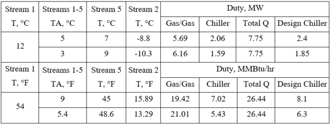
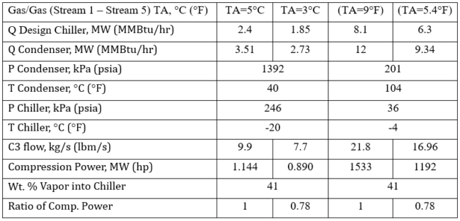
Table 2 indicates that by lowering Gas/Gas TA from 5°C (9°F) to 3°C (5.4°F), the compression power is reduced to 0.78 of the base case of TA = 5°C (9°F). For greenfield projects, even though Gas/Gas CAPEX goes up, the chiller and condenser CAPEX go down. For compressor both CAPEX and OPEX go down. For the existing units the saving will be only on compressor OPEX.
An optimization study can be completed costing out the various size options of the gas/gas heat exchanger temperature approach, and the propane chiller / refrigeration equipment capital cost and operating costs to determine the most cost-effective installation. For an example see June 2019 [3] Tips of The Month.
In fact, for all of the options discussed in this tip, completing the optimization studies along with equipment pricing and operating cost estimates can be used to determine the best process configuration for the various options.
Table 2. Impact of Gas/Gas HX TA on compression power and condenser duty
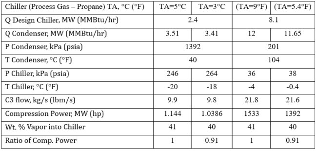
Option 2: Chiller TA Between Process Gas and Propane:
Propane vaporizing temperature and pressure are a function of process gas temperature and chiller TA. Lower TA results in higher chiller temperature and pressure. Therefore, suction pressure goes up and reduces the compressor power. Table 3 indicates that by lowering process gas-propane TA from 5°C (9°F) to 3°C (5.4°F), the compression power reduced to 0.71 of the base case of TA = 5°C (9°F). For greenfield projects, chiller and condenser CAPEX goes down and compressor CAPEX and OPEX go down. For existing units, the saving will be only on compressor OPEX.
Table 3. Impact of process gas-propane (chiller) TA on compression power and condenser duty
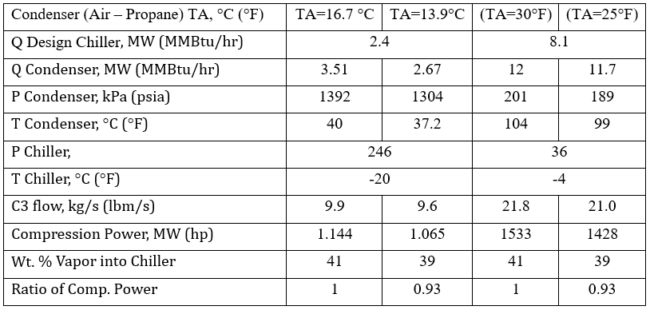
Option 3: Condenser TA Between Air and Propane:
Propane condensing temperature and pressure are a function cooling media (air) temperature and condenser TA. Lower TA results in lower propane condensing temperature and pressure. Therefore, discharge pressure goes down and reduces the compressor power. Table 4 indicates that by lowering process gas-propane TA from 16.7 to 13.9°C (30 to 25°F), the compression power reduced to 0.72 of the base case of TA = 5°C (9°F). For greenfield projects, the condenser CAPEX goes down and compressor CAPEX and OPEX go down. For existing units, the saving will be only on compressor OPEX.
Table 4. Impact of air-propane (condenser) TA on compression power and condenser duty
Option 4: A Flash Tank with Two Stages of Compression Economizer [1]:
Figure 3 presents a refrigeration system employing one flash tank economizer. In this system, the saturated liquid refrigerant leaving the accumulator is expanded across a valve to an intermediate pressure where vapor and liquid are separated. This separator liquid is expanded across the second valve to chiller pressure while the separator vapor goes to the compressor inter-stage suction. The refrigerant entering the chiller now has a higher liquid content. This reduces the refrigerant circulation rate through the chiller as well as the first stage compressor power requirement. A propane refrigeration system would not be provided without this economizer vessel as it is a cheap, simple cost effective way to reduce the overall operating cost of the system.
The pressure at point E is typically set at a value that minimizes the total compression power and is compatible with the compressor design. Total power is minimized when the first stage and second stage power are equal, but this leads to a first stage compression ratio that is higher than the second stage which may not be compatible with the compressor design, particularly when a centrifugal compressor is used. For purposes of preliminary calculations, assuming an equal compression ratio between compression stages is adequate.
Figure 3 also presents the simulation results for an interstage pressure of about 595 kPa [86 psia] which yield equal compression ratio.
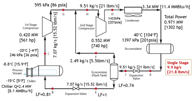
Figure 3. An example of a flash tank with two stages of compression economizer
Option 5: Energy Integration – Utilizing an Available Cold Process Stream
The residue gas (Stream 5) of Figure 2 at T = 7 °C (45 °F), P = 7500 kPa (1088 psia), and a condenser TA= 5°C (9 °F) can be utilized as cooling medium for condensing propane at 12 °C (54 °F) prior compression to pipeline inlet pressure. Figure 3 presents the process flow diagram utilizing Stream 5 cold temperature of Figure 2 for condensing propane in a simple refrigeration system.
Tables 5a (SI units) and 5b (FPS units) present the simulation results for three cases; (1) a simple refrigeration system as the base case, (2) a flash tank economizer of option 4, and (3) the simple refrigeration plants shown in Figure 4. Table 5 indicates that the simple refrigeration utilizing the cold process stream for condensing propane requires the lowest power followed by the flash tank economizer. Compared to the base case, the power reduction ratio is 0.47 and 0.85 for the simple system with cold stream for condensing propane and the flash tank economizer, respectively.

Figure 4. Utilizing Stream 5 cold temperature for condensing propane in a simple refrigeration system
Table 5a. Comparison of flash tank economizer and cold gas condenser with the base case

Table 5b. Comparison of flash tank economizer and cold gas condenser with the base case

Summary:
This tip demonstrated the impact of several key parameters on the compression power of a mechanical refrigeration system (for a HCDP control plant) and the following observations were made.
1. Option 1: The cold separator temperature (chilling temperature) and the chiller duty are the key design variable and have a significant impact on the compression power of mechanical refrigeration.
• Chiller duty may be reduced by utilizing a Gas/Gas HX and/or gas-liquid HX with optimum temperature approach (TA) upstream of chiller (Figure 2 and Tables 1 & 2).
• Lower TA increases the Gas/Gas HX duty but lowers the chiller duty (Table 1).
2. Option 2: The lower chiller TA between gas-propane, the higher chiller temperature and pressure which reduces compression power. (Table 3).
3. Option 3: The lower condenser TA between cooling media-propane, the lower condenser temperature and pressure which reduces compression power. (Table 4).
4. Option 4: Use of a flash tank economizer reduces compression power (Figure 3, Table 5)
5. Option 5: Using an available cold residue gas as cooling medium for condensing propane in a simple refrigeration system reduces compression power considerably (Fig. 4, Table 5).
To learn more about similar cases and how to minimize operational problems, we suggest attending our G4 (Gas Conditioning and Processing), G5 (Practical Computer Simulation, and Applications in Gas Processing) courses.
Written By: Mahmood Moshfeghian, Ph.D.
References:
1. Campbell, J.M., “Gas Conditioning and Processing, Volume 2: The Equipment Modules,” 9th Edition, 3rd Printing, Editors Hubbard, R. and Snow–McGregor, K., Campbell Petroleum Series, Norman, Oklahoma, PetroSkills 2018.
2. Moshfeghian, M., http://www.jmcampbell.com/tip-of-the-month/2020/03/impact-of-process-gas-pressure-on-the-performance-of-a-mechanical-refrigeration-plant/ , PetroSkills -John M. Campbell Tip of the Month, March 2020.
3. Moshfeghian, M.,http://www.jmcampbell.com/tip-of-the-month/2019/06/impact-of-temperature-approach-of-the-heat-exchangers-on-the-capex-and-opex-of-a-mechanical-refrigeration-plant-with-meg-injection/, PetroSkills -John M. Campbell Tip of the Month, June 2019
4. GCAP 9.3.2, Gas Conditioning and Processing, PetroSkills/Campbell, Tulsa, Oklahoma, 2020.
5. Campbell, J.M., “Gas Conditioning and Processing, Volume 1: The Fundamentals,” 9th Edition, 3rd Printing, Editors Hubbard, R. and Snow–McGregor, K., Campbell Petroleum Series, Norman, Oklahoma, PetroSkills 2018
