In Part 1 of this Tip of the Month Series, a basic review of the APCI C3/MR process was provided. In addition, a brief introduction into the global LNG trade was discussed. Part 1 cited many Liquefaction Technologies available for LNG processing, showing that the most commonly applied LNG liquefaction technology was the APCI C3/SMR(MR) process which is present in over 40 % of the worlds’ 33 existing LNG Plants during 2018 – 2019.
As stated in Part 1, the existing APCI C3/MR liquefaction process has been proven to be very energy efficient, thermodynamically stable, operator friendly, as well as operationally reliable, and applies well known refrigerant components for the process. The current Part 2 of the Tip seeks to provide an insight into the operation of the propane pre-cooling cycle of an APCI Single Mixed Refrigerant (SMR/MR) facility processing 680 MMscfd (19.21 x 10⁶ std m3/d) of inlet gas. This is roughly equivalent to 14,000 tpd, or 5.1 mtpa of LNG production.
For this case study, the Inlet Process Gas has a composition very similar to the previous compositions and shown in Part 1 of the Tip.
An Analysis of the APCI C3/MR Propane Pre-cooling cycle
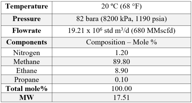
Table 1 [1] provides the assumed inlet gas composition and operating conditions for the assumed feed gas to the facility. Free liquids are separated from the inlet gas, in the inlet separator, and the gas is filtered to remove any particulates. From there, the gas flows to the acid gas removal unit to remove the acid gas components (H2S / CO2) to an acceptable level. For simplicity, the gas composition provided does not show the ppm values of H2S and CO2 that were present that required treating.
Table 1. Inlet Gas conditions and compositions [1]
The feed gas temperature increases when it flows through the amine contactor in the Acid Gas Removal Unit. The reaction between the amine and the acid gas components is exothermic. The process gas conditions entering the first Chiller are shown in Table 2. At this point, roughly 0.28 x 10⁶ std m3/d (10 MMscfd) of fuel gas has been taken off from the inlet stream, in addition, the gas pressure has also been adjusted to be at the optimum liquefication train operating pressure. The locations of the stream conditions are summarized on the process flow diagram shown in Figure 1.
Table 2. Treated Gas to First Propane Chiller
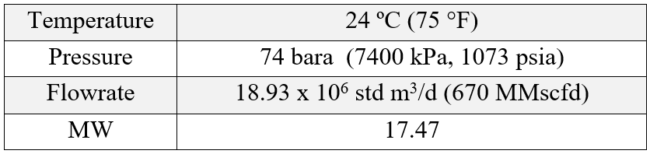
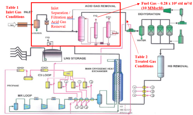
Figure 1. Process Flow Diagram – Inlet Gas Treating Conditions [2]
This first propane Chiller operates at 660 kPa (96 psia) and 11°C (52°F). The gas is cooled to 18°C (64°F), with a cold end temperature approach on the chiller of roughly 7°C (12°F). There is a small pressure drop of the process gas through the gas chiller, resulting in an outlet process gas pressure of 7300 kPa (1059 psia).
The gas then flows through the molecular sieve dehydration unit, and then on to the mercury removal unit (MRU). The assumed mercury content of the gas is 110 μgm/Nm3, which corresponds to roughly 0.01 ppm, or virtually nil in terms of mole %. For the assumed inlet flow rates, and mercury concentration, this translates into 0.16 kg Hg/d (0.35 lbm Hg/d). Often times, a mercury removal unit bed life could be on the order of 14 – 15 years. It really depends on how much mercury is present in the feed gas, and how the original guard bed was designed.
The stream conditions are now defined in Figure 2.
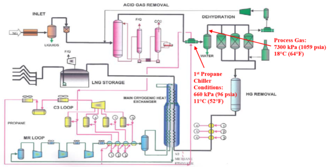
Figure 2. Process Flow Diagram – Process Gas Conditions after the first Propane Chiller [2]
Now let’s take a deep dive into the Propane Refrigeration – Pre-Cooling portion of the plant.
Propane Refrigerant Operating Conditions:
It is assumed that propane is available locally for delivery to the plant as 99-99.5 pure C3. Within the Process Gas cooling cycles, effective application of propane thermodynamic performance is essential. A selection five (5) operating pressure stages are established for the propane processing cycle for both the MR, and Process Gas. The final Propane compression stage is designated to be readily condensable via aerial cooling units, and not to be considered a “cooling level”. The four (4) compression suction stages are also designated for cooling of the process gas, (PG) as well as the Mixed Refrigerant (MR).
These cooling operation pressures and temperatures will be referred to as LEVELS so as to differentiate compression “stages”, vs. cooling “levels”. Optimization of Propane compressor horsepower often is the driver that sets the facilities operating pressures and temperature for the four (4) chilling stages. Total propane mass flow required can be estimated once both process gas, and MR mass flows and cooling heat loads have been established. With reference to Figure 3 [2], that depicts the typical APCI C3MR Plant under consideration, Table 3 [2] summarizes the existing Propane pressure, and temperature conditions applicable to the Plant Operations for compression, and chilling of the Process Gas, as well as the MR pre-cooling and partial condensation:
Table 3. Propane Refrigeration Conditions for a Typical APCI C3MR Plant [2]
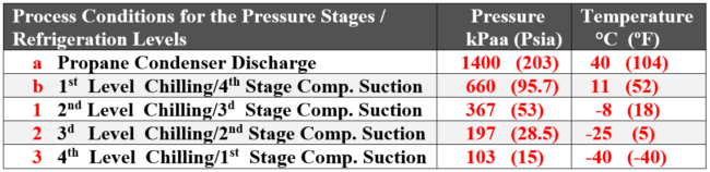
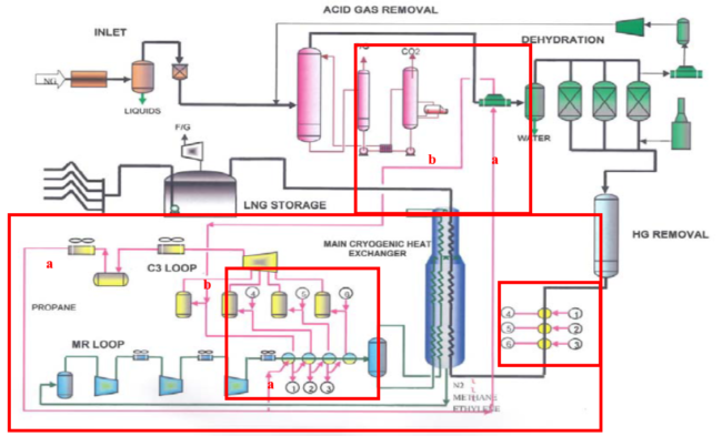
Figure 3. Propane Pre-cooling Cycle highlighted – APCI C3 MR PFD [2]
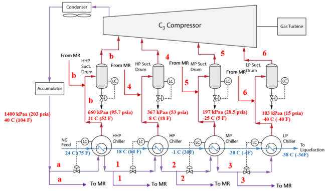
Figure 4. Simplified Process Gas Propane Refrigeration Pre-Cooling Schematic [2]
Notice in Figure 4, the PG temperatures leaving each chiller are noted in light blue text. Understanding what the PG gas temperature and pressure is leaving the chillers allows one to estimate the duty of each of the PG propane chiller services. Also note, that at each chilling stage there will be a resulting “unused” liquid propane that is required to provide cooling duty to the subsequent lower pressure and temperature chilling levels. In effect, each of the propane chillers is also functioning as an economizer, which reduces the overall required propane refrigeration compressor horsepower. Thus, the 3d stage propane chilling at 197 kPaa (28.5 psia), and -25 ºC (5 ºF) denoted by the point of reference “2” is metered and directed to the MR chiller, as well as to the PG Chiller. As seen the propane vapor of this pressure level is directed to the compressor suction scrubber denoted as “5”. Finally, the 4th stage propane chilling at 103 kPaa (15 psia), and – 40 ºC (- 40 ºF) are indicated by point “3” and the resulting vapors are directed to the Compressor Suction scrubber indicated by “6”. All the remaining liquid propane at the 3d stage pressure/temperature chilling level is converted to a vapor phase at the 4th stage chilling with no further liquid propane required.
An important point to consider is that the required propane liquid mass flow rate required to provide the process gas, and mixed refrigerant heat loads for all four (4) chilling levels will not be the final TOTAL propane mass to be handled by the four (4) stages of compressor operation due to the amount of propane vapor that flashes off at each level of refrigeration.
With understanding the basic thermodynamic principles of the propane refrigeration, one can set up the APCI C3MR propane pre-cooling process on a propane P-H diagram as shown below in Figure 5.
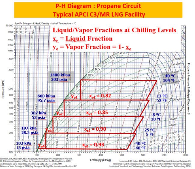
Figure 5. PH Diagram for Propane (SI and FPS units shown); kJ/kg (0.433 BTU/lbm) [3]
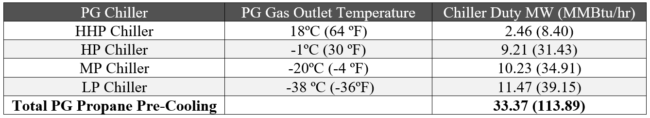
The detailed hand calculations to estimate the required propane flow rate for the PG service is out of the scope of this TOTM. However, a summary of the total cooling demand required for the pre-cooling propane service is provided in Table 4.
Table 4. Propane Pre-Cooling Chiller Summary [4]
Now that the propane pre-cooling section is summarized, we can take a look at the cooling demand that is provided by the MR.
Main Cryogenic Heat Exchanger Energy Balance for the PG:
The following conditions are present for the PG entering the MCHE:
► Qg (Gas Rate) = 670 MMscfd (~19 x 106 std m3/d)
► Qgm (Gas Mass Rate) = 586 000 kg/hr (1.29 x 10⁶ lbm/hr)
► Inlet Pressure = (7000 kPa; 1015 psia)
► Inlet Temperature -38 ºC (-36.4 ºF)
► Discharge Pressure = (5300 kPa; 769 psia)
Figure 6 [4] presents the results of the first calculations at the above stated conditions for the PG indicating an energy load of – 355.179 x 10⁶ kJ/h (98.6 MW). This value corresponds to the heat to be removed from the PG resulting in the existing LNG at tower top conditions before the Isenthalpic expansion to atmospheric pressure and approximately -161 ºC (259 ºF). This heat must be removed by the two-phase MR entering as a cold liquid phase from the inlet at the bottom of the MCHE and progressing as a cold liquid through the “Warm Bundle” in the lower part of the exchanger. The liquid MR undergoes at JT expansion to pre-cool the incoming PG and upward flowing vapor phase MR. The cold vapor phase MR proceeds vertically through the exchanger to the “Cold Bundle” where it also undergoes a JT expansion resulting in temperature well below -170 ºC (-274 ºF). The MR exits the exchanger at low pressures and at temperatures some 5 – 8 ºC (9 -14 º) cooler than the incoming Process Gas.
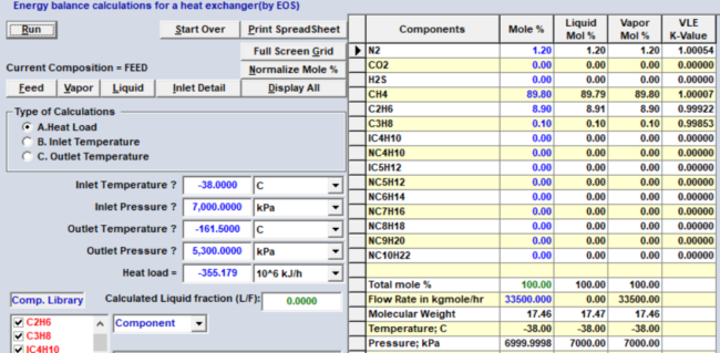
Figure 6 [4]: Determination of the Process Gas (PG) Heat Load in the MCHE
The second calculation to be carried out would be to estimate the required MR rate that will yield the required heat exchange capacity to absorb the required MW (MMBtu/hr) of energy from the PG. Completing the MR refrigeration flow rate calculations is complex and requires the use of a process simulator. These calculations are out of the scope of this tip.
However, it is interesting to note that the propane pre-cooling cycle provides roughly 34% of the total cooling duty to the PG (propane cycle + MCHE = 33.4 + 98.6 = 132 MW).
It should also be noted that the heat sink to the propane refrigeration is atmosphere, and the heat sink for the MR is the propane refrigeration unit. For a plant running at these conditions, the estimated total duty of the propane cycle to provide the MR cooling and condensation is roughly 117.6 MW (401.4 MMBtu/hr). The propane is essentially removing the heat that the MR is absorbed in the MCHE from the PG, thus it makes sense that the propane duty required by the MR is significantly greater than that required to pre-cool the incoming natural gas.
Summary of Part 2 of the Tip of The Month
Part 2 has attempted to focus on a portion of the principal operational conditions and their functions as related to the PG, and MR in a typical APCI C3MR LNG facility. In this review, the following crucial items have been addressed for this purpose:
A typical APCI C3MR plant was chosen with corresponding inlet conditions considered for a Gas at 680 MMscfd (19.28 x 10⁶ std m3/d) to be converted to 670 MMscfd (18.93 x 10⁶ std m3/d) after initial Plant processing and preparation for liquefaction in the MCHE. The typical operational array of pressures and temperatures were discussed and reviewed.
A simplified analysis related to the Plant’s propane chilling configuration for a typical four (4) compression stage, and four (4) chilling (stage) level operation with corresponding pressures and temperatures was shown and discussed.
The thermodynamic criteria was discussed for determination of the Process Gas heat loads at each Chilling Level was presented on the propane Pressure-Enthalpy diagram. The temperatures, and pressures for the PG, were established in preparation for entry to the MCHE.
An energy heat load was computed for the PG with given inlet and outlet temperature and pressure at entering and MCHE tower top conditions. The heat required to be removed from the Process Gas to produce LNG was established.
To learn more about LNG, we suggest attending our G2 (Overview of Gas Processing), G29 LNG (Short Course: Technology and the LNG Chain) and G4 LNG (Gas Conditioning and Processing-LNG Emphasis) courses.
Written By: Dr. Frank E. Ashford & Kindra Snow-McGregor, P.E.
References
1. Typical PROCESS GAS, and SMR MEDIUM Compositions for APCI Process: Private Communication
2. Typical APCI C3MR LNG Facility LNG: Private Communication
3. Gas Conditioning and Processing: Vol 2 (Edition 9.3) “The Equipment Modules”
4. PetroSkills/John M. Campbell: GCAP 9.
