Overview of Gas Lift; Part 3: Operational Field Procedure for Identifying, Selecting, and Optimizing a Gas Lift Well
March 1, 2022
|
Tip of the Month
Part 3 of the Overview of Gas Lift series has procedures for identifying, selecting, and optimizing technical as well as field operations for a gas lift well.
View Article
Overview of Gas Lift; Part 2: Operational Fundamentals for the Performance of a Gas Lift Well, Related to Choke Flow, Single Phase Gas, and Multiphase Flowing Gradients
February 3, 2022
|
Tip of the Month
In the Part 1 of this Series on Gas Lift History and Basic Well Parameters, an attempt was made
to bring into focus the primary “state of affairs” of Gas Lift operations in the USA.
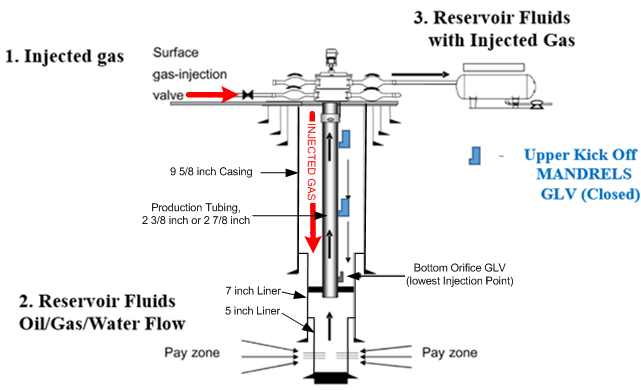
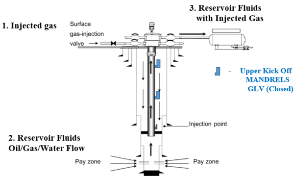
Part 2 will discuss basic Gas Lift well casing and tubing components, and their operational
function, as well as Choke Flow relationships in Gas Lift wells.
In the Firs...
View Article
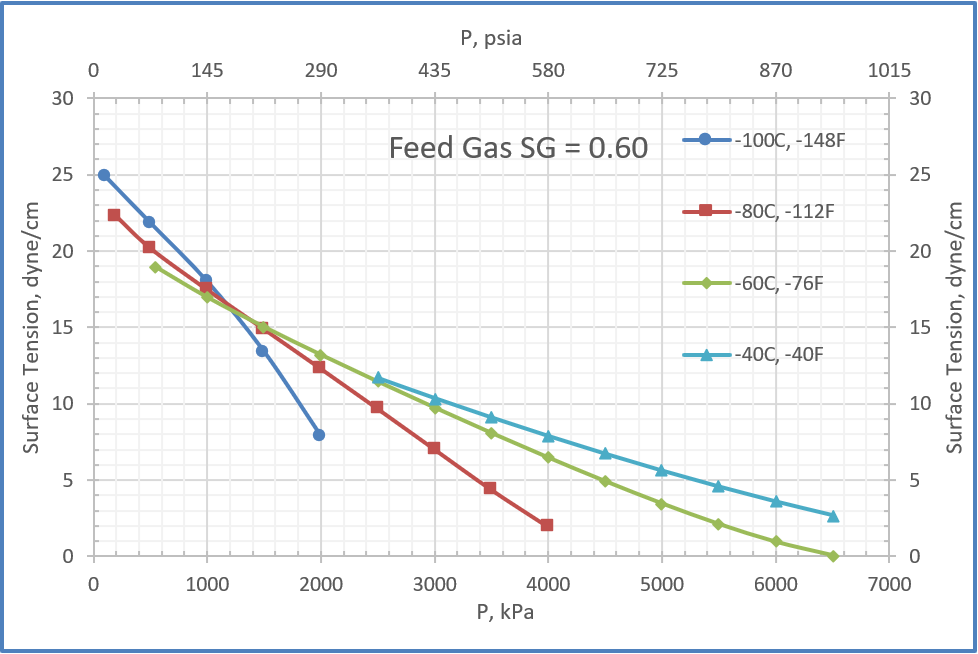
Estimation of Surface Tension of Hydrocarbon Liquids in Equilibrium with Natural Gas Mixtures
January 6, 2022
|
Tip of the Month
In December 2021 tip of the month (TOTM), we presented two simple empirical correlations for estimating pure liquids surface tensions of the paraffins methane through n-octane. The two correlations express the surface tension as a function of the reduced temperature and molecular weight with only two (first correlation) and four (second correlation...
View Article

Estimation of Surface Tension of Pure Paraffin (Alkane) Hydrocarbons
December 7, 2021
|
Tip of the Month
Two simple empirical correlations and a corresponding states method reported in the literature are used to estimate pure liquids surface tensions for the paraffins methane through n-octane. The two correlations express the surface tension as a function of the reduced temperature and molecular weight with only two (first correlation) and four (secon...
View Article
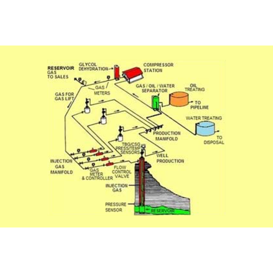
Overview of Gas Lift; Part 1: Gas Lift History, Fundamentals, Mandrels, Valve Types, and a Typical Field Installation
November 2, 2021
|
Tip of the Month
In this Part 1 presentation of the initial Gas – Lift series, and effort has been made to provide for initial orientation regarding the important Gas – Lift history, initial background, initial production efforts, Gas – Lift components, and design criteria. Oil and Gas production has been an integral part of the World’s energy based economy for ov...
View Article

Clean Energy Needs an “All of the Above” Approach to Ensure Availability and Reliability
October 4, 2021
|
Tip of the Month
This Tip of the Month will discuss energy issues in the U.S, and highlight why there must be an “all of the above” approach to electricity generation technologies to ensure availability and reliability. The type of technology selected should be based upon what the local resources and environment can provide as there is no silver bullet, or one siz...
View Article