Oil Field Water Scaling Case Studies
Scale Overview
Most produced and sea waters contain many dissolved (soluble) minerals/components. The positive (+) charge constituents like Na+ and Ca++ are called cations. The negative (-) charge constituents like Cl- and CO− −3 are called anions. Table 1 shows typical mineral constituents in produced and sea waters. Primary salts found in produced waters are ~ 75 wt% NaCl, ~ 20 wt% CaCl2 and ~ 5 wt% MgCl2.
Table 1. Typical mineral constituents in produced and sea waters

What is scale?
When the solubility limits of one or more components is exceeded, scale forms. Table 2 shows solubility of typical scales at 25 °C [77 °F]. Scale is precipitation and deposition of inorganic minerals from brine.
Table 2. Solubility of typical scales

How does it occur?
Scaling is usually associated with precipitation. It is recognized that precipitation does not necessarily lead to scaling, but scaling is often thought to result from precipitation followed by adhering of the precipitates to surrounding surfaces. Scaling which occurs at ambient pressures and static conditions may not necessarily occur at elevated pressure and dynamic flows, and vice versa. Scale causes corrosion, equipment damage, and flow restriction and therefore lowering the production rate. Various mechanisms can cause scale formation.
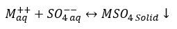
a. Calcium carbonate (Calcite): CaCO3 scale can occur if reaction 1 is shifted to the right.
(1)
 (1)
(1)CaCO3 scale may form by mixing two dissimilar waters, but often caused by pressure reduction and/or temperature increase which causes the evolution of carbon dioxide (CO2) and an increase of pH in produced water. Temperature effects are equally important because calcium carbonate (CaCO3) is less soluble at higher temperatures and will form a deposit in heat exchangers, heaters, and treaters leads in ineffective operation and loss of revenue.
b. Sulfate (Ba, Ca, Sr): In reaction 2, M can be either of Calcium, Barium, or Strontium (Ca, Ba, Sr) forming CaSO4, BaSO4, or SrSO4.
(2)
 (2)
(2)Sulfate scales are typically caused by the mixing of two different waters—most often formation/produced water and sea water.
For example, seawater with a small concentration of Strontium (Sr++), no Barium (Ba++) but high concentration of Sulfate (). On the other hand, a high salinity produced water has no Sulfate () but a high concentration of Strontium (Sr++) and Barium (Ba++). If these two waters are kept separately, they do not form scale, but if they are mixed cause severe Barium Sulfate (BaSO4) and Strontium Sulfate (SrSO4) scale formations.
 ). On the other hand, a high salinity produced water has no Sulfate (
c. Sodium chloride (Halite): NaCl is not very common.
(3)
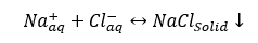 (3)
(3)Remember Sodium chloride, NaCl, solubility is 357,000 mg/l in water at 25 °C (77 °F). This is a very high solubility, but NaCl may precipitate out due to temperature reduction, or may also precipitate due to water flash-off caused by pressure reduction of high temperature produced fluids.
How is it Controlled?
Scale control can be divided into two categories, chemicals, and none-chemicals. The chemicals can be scale inhibitors to prevent scale deposition. They are applied by continues injection in downhole or surface equipment like piping and heat exchangers. In formation, inhibitors are applied by “squeeze” treatment. If scale has been deposited already, we apply scale removal chemical (Acids or Chelating Agents).
The three types of none-chemical categories for scale control are:
- Desulfation (removal of sulfate ion ()) of injected water by membrane process to prevent barium/strontium scale formation. Reducing ~2600 mg/l to < ~30 mg/l ()
- Dilution, to prevent halite (NaCl) formation by dilution below solubility limits with relatively “fresher” water.
- Mechanical removal of scale by abrasive jetting and or impact bits/milling
Where does it occur?
Scale deposition can occur in reservoir/formation, and production facilities such as:
A. Hydrate inhibition using MEG, during the rich solution regeneration at low pressure and high temperature. For more detail, refer to the three options of reference [1].
1. Conventional regeneration of rich MEG solution – by water removal only
2. Full reclamation – by evaporating the total rich MEG feed
3. Slip-stream salt removal
B. Hydrae inhibition of sour gas using MEG, during a close – loop regeneration and reclaiming system. For more detail refer to reference [2]
C. Water flooding/injection for enhanced oil recovery where different waters are mixed. A computer software can be used to evaluate the experimentally measured chemical analyses of effluent waters and that of formation water and determine the tendency of scale formation. The scaling tendency for the commingling of individual effluent waters with formation water at reservoir temperatures and pressures may also be predicted. Salman et. al. investigated the scaling tendency for four Gathering Centers (GC) of an oil field in the State of Kuwait [3]. Attention was made on the scaling tendency of CaCO3 and BaSO4 for various mixing proportions of effluent water with formation water.
To demonstrate the steps involved, this tip of the month reports the summary of results by Salman et. al.’s computer scaling study for four Gathering Centers [3]. In a follow-up tip, we will focus on the scaling during regeneration of rich MEG feed [1, 2].
Water analysis
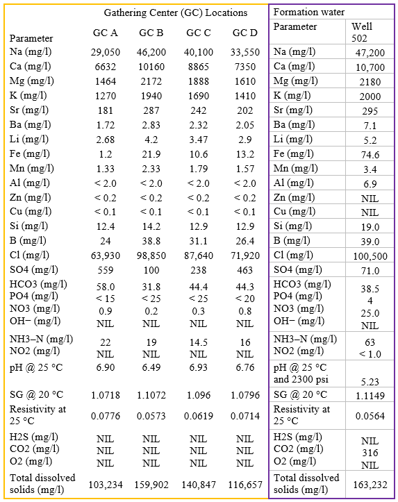
Effluent water and formation water analyses used as input to the computer simulations are shown in Table 3.
Table 3. API analyses of effluent waters for GC's and formation water [3]
Why and how scaling tendency was investigated?
Compatibility or scaling tendency of effluent waters with formation waters in the oil field will be a major factor in determining the feasibility of produced water re-injection and defining engineering solutions for the injection system. Salman et. al. [3] performed a computer scaling study on the effluent waters from Gathering Centers (GC's) A, B, C, and D. Four cases were considered:
1. Scaling tendency of individual effluent waters at surface conditions.
2. Commingling of effluent waters with each other prior to injection.
3. Scaling tendency of effluent waters at reservoir conditions.
4. Commingling of effluent waters with formation water at reservoir conditions.
Computer scale program
The program (OKSCALE) used by Salman et. al. [3] to perform the scaling predictions is a dedicated scaling program developed by the University of Oklahoma [4]. This program only considers calcium carbonate, barium sulfate, calcium sulfate and strontium sulfate scales; however, it offers several advantages over other commercially available scaling software [3, 4]. The list of OKSCALE assumptions is also available in reference [3].
Geochemical modelling conditions and cases
A logical strategy is to trace the path of the injection water from its abstraction and treatment to the point where it mixes with the formation water, in the absence of any scale inhibitor treatment. In addition, for this study, consideration should be given to the fact that the injection water will be a mixture of effluent waters from all operating GCs in the field.
Therefore, computer scaling predictions were performed on the following waters and conditions to simulate operating conditions:
1. Self-scaling potential of effluent waters for each GC monitored
2. Injection plant downstream of the injection pump for individual effluent waters. This simulation assumes an injection pressure of 175 bars and that the effluent water has not reached thermodynamic equilibrium with the formation (i.e., the assumed temperature is that measured at the surface).
3. Scaling potential of mixed effluent waters at both surface and injection conditions to simulate mixing of effluent waters prior to and during injection.
4. Mixing of formation water and individual effluent waters at reservoir conditions (temperature=59 °C = 138 °F, pressure=175 bar = 2538 psia)
Results
The results of the computer scaling study by Salman et. al. [3] are reported below. None of the cases modelled below predicted any CaSO4 or SrSO4 scales and these are not discussed further.
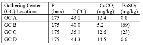
Case 1: Self-scaling potential of effluent waters at surface conditions
Table 4 summarizes the results of the effluent water self-scaling potential simulation which were performed at surface conditions. These results predict that the effluent waters are slightly supersaturated with respect to both CaCO3 and BaSO4 and small amounts of
these scale deposits are predicted under these conditions.
Table 4. Self-scaling potential of effluent at surface conditions [3]
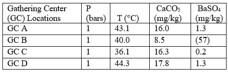
Figures in parentheses indicate undersaturation. Values are % off saturation.
No CaSO4 or SrSO4 scales are predicted.
Case 2: self-scaling potential of effluent waters
Table 5 summarizes the results of effluent water self-scaling potential simulations performed under conditions expected in the injection wells. It should be noted that the assumed temperature for these simulations was that measured at surface during the field work which implies that during injection the water will not have reached thermodynamic equilibrium with the formation.
The bottomhole temperature within the injection well and near wellbore area will be between that of the injection temperature and the general reservoir temperature— depending on flow rate and specific heat capacity of the formation. The results for this case are very similar to those for case 1, in general, with minor amounts of CaCO3 and BaSO4 scales being predicted during injection of the effluent waters.
Table 5. Self-scaling potential of effluent waters at injection conditions*[3]
*Assumes that the injection temperature is equal to that measured at surface. The injection temperature will be between that measured at surface and the reservoir temperature (59 °C for this study), depending on flow rate and specific heat capacity of the formation. Figures in parentheses indicate undersaturation. Values are % off saturation.
Case 3: mixing of effluent waters prior to end during disposal
Cases 1 and 2 considered the scaling potential of individual effluent waters under different conditions. However, during operation, the effluent waters may be commingled prior to or during injection. This case considers the compatibility of the effluent waters with respect to each other. For this simulation mixing of only two effluent waters was considered in any detail. The two waters selected here for a detailed study were the effluents from GC A and GC B because they represent extreme chemical compositions of effluent waters from all the GC's sampled. The modelled results of mixing these waters are presented in Table 6 and suggest that minor amounts of CaCO3 and BaSO4 may form during commingling of the effluent waters. Table 6 indicates that at higher pressure the scaling potential decreases. Again, the amount of these scales is predicted to be very low. The impact of pressure and temperature on the water scaling using theoretical grounds has been presented in detail by Atkinson and Mecik [4].
Table 6. Scaling potential of commingled GC A and GC B effluent waters [3]
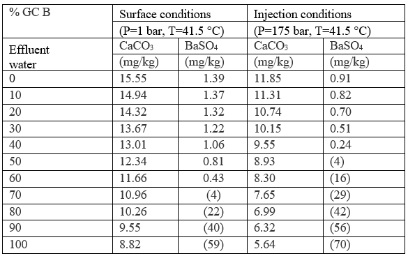
Figures in parentheses indicate undersaturation. Values are % off saturation. No CaSO4 or SrSO4 scales are predicted.
Case 4: mixing of effluent water with formation water
During injection, the injection waters will displace all formation water in the near well bore region. However, as the injected waterfront moves into the formation it will commingle with the formation water. This commingling can lead to scaling problems if the injection water and formation water are incompatible. This case models the effect of commingling individual effluent waters with formation water at reservoir temperatures and pressures. The results of these simulations are reported in Table 7 and Figures. 1 and 2 and suggest that when the amount of commingled injection water is high (typically greater than 50%) minor amounts of CaCO3 scale will form. The predictions for BaSO4 scaling depend on the assumed composition of the injection water. For example, if the injection water is assumed to be from GC A or GC D small amounts of BaSO4 scale is predicted to occur on the commingled water above 50% injection water. On the other hand, if the injection water is assumed to be represented by GC B or GC C effluent waters, BaSO4 is predicted to be undersaturated regardless of the amount of injection water. The formation water is undersaturated with respect to CaCO3 and BaSO4 and no scaling of these minerals is predicted below approximately 50% injection water. There is an important difference in the aqueous chemistry for sulfate scales and carbonate/sulfide scales that is why two different trends are observed in Figures 1 and 2. While the sulfates are independent of pH, there is a strong pH dependence on the solubility of carbonates/sulfides. This makes prediction of carbonates/sulfides far more complicated than prediction of sulfates since it is necessary to calculate both pH and the concentrations of all the carbonate/sulfide species. The presence of other acids, such as organic acids, must also be included in the calculations. One of the main reasons for CaCO3 precipitation during oil recovery is the pH increase due to loss of CO2 from the aqueous phase to the oil and gas phase as the pressure drops.

Figure 1. CaCO3 scale prediction at reservoir conditions Figure 2. BaSO4 scale prediction at reservoir conditions (Commingling of effluent and formation waters). (Commingling of effluent and formation waters).
Table 7. Scaling potential of commingled effluent water and formation water

Figures in parentheses indicate undersaturation. Values are % off saturation. No CaSO4 or SrSO4 scales are predicted.
Discussion
The results of the computer scaling study predict minor amounts of CaCO3 and BaSO4 scaling in the injection system. These predictions are extremely marginal; however, in the absence of other information, predictions should be taken to prevent scaling. This should include the facility to inject suitable scale inhibitors into the GC disposal waters prior to or in the proposed water disposal plant.
It is emphasized that the results presented in this section are marginal and are predictions only. Due to uncertainties in assumptions made in the scaling program's thermodynamic database it is entirely possible that CaCO3 and BaSO4 scaling will not occur.
At these marginal levels, the only way to confirm the scaling tendency of the waters is to perform a series of laboratory scaling experiments. This study has only considered the compatibility of waters with respect to ‘common’ scale deposits (CaCO3, CaSO4, BaSO4, and SrSO4). However, given the presence of H2S in some of the effluent waters some consideration should be given to the possibility of iron sulfide (FeS) scaling.
H2S and Ferrous Iron (Fe (II)) concentrations in the effluent waters were low and where H2S concentrations were high (50 mg/l in GC A wet tank) Fe (II) concentrations were low (0.1 mg/l in GC A wet tank). Conversely, where the Fe (II) concentrations were high, the H2S concentrations were low. The limited availability of Fe (II) and for H2S suggests that there is limited potential for FeS scaling from the waters collected during this study. However, this does not preclude a possible problem with FeS scaling in the GC.
Conclusions and recommendations [3]
1. Computer scaling predictions have been performed on a few aqueous systems which will be encountered during disposal of effluent waters into the Fourth Sand Formation.
2. The effluent waters are, self-scaling with respect to calcium carbonate and barium sulphate. However, the amount of these scales predicted is very small and it is quite possible that no scaling will occur. A series of laboratory scaling experiments is the only way to confirm the scaling tendency of these waters.
3. The Fourth Sand Formation water is undersaturated with respect to all the common scaling minerals.
4. Commingling of the effluent water and formation water may lead to calcium carbonate and barium sulphate scaling above 50% effluent water. However, these predictions are, again, marginal.
To learn more about similar cases and how to minimize operational problems, we suggest attending our G4 (Gas Conditioning and Processing), PF81 (CO2 Surface Facilities), PF4 (Oil Production and Processing Facilities), courses.
By Mahmood Moshfeghian, Ph.D.
References:
1 S. Brustad, S., Løken, K. P., and Waalmann, J.G., “Hydrate Prevention using MEG instead of MeOH: Impact of experience from major Norwegian developments on technology selection for injection and recovery of MEG,” Offshore Technology Conference held in Houston, TX, U.S.A., 2–5 May 2005.
2. Al-Mudabegh, S. H., Rithauddeen, M. A., and Alawi, M., “Aramco outlines best practices for sour-gas feed MEG system,” Oil & Gas Journal, Oct 3, 2022.
3. Salman, M., Qabazard, H, and Moshfeghian, M., “Water scaling case studies in a Kuwaiti oil field,” Journal of Petroleum Science and Engineering 55, 2007.
4. Atkinson, G., Mecik, M., “The Chemistry of scale prediction,” J. Pet. Sci. Eng. 17, 1997.
