This Tip of the Month (TOTM) discusses design and operational considerations of surface facilities for unconventional light oil shales and answers for the following questions:
- Are you having vapor pressure issues in the winter? One operator had 100,000 bpd shut in for a month.
- Are your tanks venting?
- Are you getting oxygen into the feed gas of your gas plant? This can cause major corrosion damage to an amine treating plant. Amines are used as oxygen scavengers and the degradation products will cause severe corrosion in hot sections of the amine plant regeneration system.
- Do you have infinite recycling?
- Are you sending your VRU compressor suction / discharge liquids back to the stock tanks? This will cause the TVP to increase. The liquids should be pumped forward into the sales gas with a positive displacement pump. See the August 2017 TOTM - Infinite Recycling impacts on Compression Systems [1].
If you are experiencing any of these issues, your surface facilities are working as designed, and the problem is the design.
A typical East Texas oil battery design will not work when processing a very light oil or condensate.
True Vapor Pressure (TVP)
What are the variables you can control to affect the stock tank vapor pressure?
- Temperature
- Pressure
- Residence Time
- Height of Liquid in the Tank
Most unconventional plays are light oil, and require an understanding of natural gas processing, phase diagrams, and infinite recycles of NGLs.
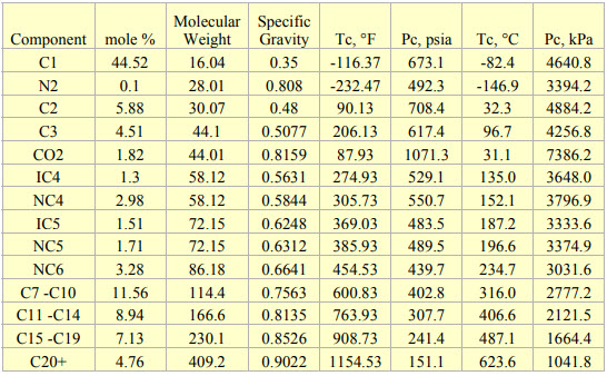
The composition and properties of the feed with Gas Oil Ratio (GOR) of 1000 SCF/STB (178 Sm3 /STm3 ) used in this tip are presented in Table 1 [2]. The tip used UniSim [3] to perform all of the process simulations.
Table 1. Composition and properties for GOR 1000 SCF/STB (178 Sm3 /STm3 ) used for simulations
In Figure 1, a heater treater operating at 120 °F (49 °C) and 65 psia (448 kPa) is flashed to a stock tank operating at 14.7 psia (101 kPa) and 110 °F (43 °C). The corresponding material streams are presented in Table 2. The resulting product has TVP of 13.56 psia (94 kPa). A key point here is that steady state simulation is a series of single point flashes. At each single point the calculations are at a liquid vapor interface. Actual vessel and tank elevations are normally not included. To get the sales TVP of 13.56 psia (94 kPa) a final flash must occur at 14.7 (101 kPa) psia and 110 °F (43 °C) at the liquid / vapor surface. If the stock tank is 20 ft (7 m) tall and is bottom fed then the fluid can have a higher vapor pressure due to the height of the tank liquid head preventing the final flash at 110 F (43 °C) and 14.7 psia (101 kPa).
Figure 1. Process flow diagram for single point flashes
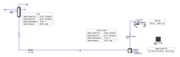
Table 2. Material streams of Figure 2 (FIELD)
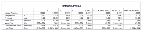
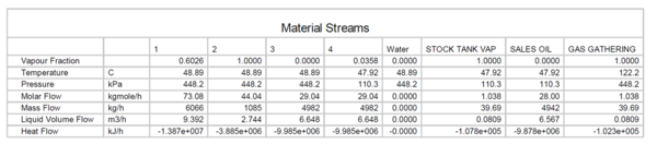
Table 2. Material streams of Figure 2 (SI)
Stock Tanks are typically 200 ft (60 M) from the heater treater. The heated oil from the heater treater will not arrive at 110 °F (43 °C) in the stock tanks through uninsulated lines in the winter when ambient conditions are -40 °F (-40 °C) and the wind is blowing. In the winter time, if the tanks are uninsulated, and unheated it’s difficult to meet the TVP specs. Simulations will show that if the tank temperature falls below 90 °F (32 °C) then the TVP spec will not be met.
Figure 2 presents typical summer operation conditions. A summary of operation considerations:
- Oxygen into the gas system to gas plant; severe damage to amine plant
- Tank venting; loss of revenue / stock tank vapor
- Tank head adds to RVP/TVP (20ft / 2.31) = 8.65 psi (160 kPa)
- Meets RVP / TVP
- No static electricity issues in bottom fed tank
Figure 2. Typical summer operation which meets TVP
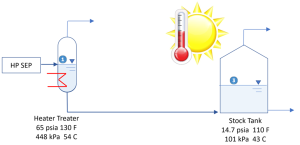
Figure 3 presents a typical winter operation conditions. A summary of operation considerations:
- Fails RVP / TVP at 90 °F ( 32 °C)and below
- Oxygen into the gas system to gas plant; severe damage to amine plant
- Tank venting; loss of revenue
- Tank head adds to RVP/TVP
- Uninsulated piping and tanks
- No static electricity issues in bottom fed tank
Figure 3. Winter operation - final flash at required conditions cannot occur and TVP is not met.
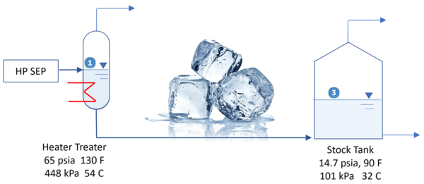
Figure 4 shows a vapor recovery tower (VRT) and its operating conditions. The heater treater and VRT to the left of the dashed red line are hot and insulated. Items to the right do not require insulation. The important flash to meet TVP occurs at point #2 and the liquid leaving the VRT meets TVP specification regardless of how cold the oil becomes flowing to the right. Practically, the three pieces of equipment (Heater Treater / VRT / Stock Tank) should be located close to each other.
The final flash from the cyclonic separator ensures that oil level tank head does not negatively impact the TVP and that the final flash will occur at the stock tank pressure of 8 oz/in2 (0.5 psia) (3.4 kPa) and high temperature. A summary of operation considerations:
- Meets RVP / TVP at point # 2
- No oxygen into the gas system
- No stock tank vapor
- 30% lower VRU power
- No tank venting
- More revenue
- Tank head no impact to RVP/TVP
- Insulated treater & VRT – not entire battery
- No static electricity issues in top fed tank
Figure 4. Vapor recovery tower (VRT)
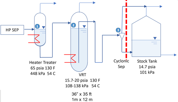
Figure 5 presents a process flow diagram for shale oil stabilization using VRT. Table 3 presents the material streams for the same PFD. Note liquid at point #2 VRT conditions meets TVP and no vapor is generated in stock tanks at 100 °F ( 38 °C) (Increased $$$).
Figure 5. Shale oil stabilization using VRT
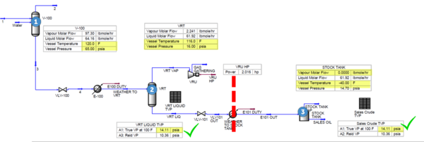
Table 3. Material streams in Figure 5 (FIELD)
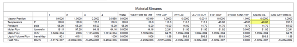
Table 3. Material streams in Figure 5 (SI)
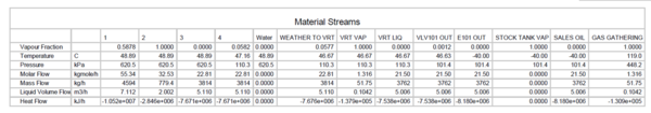
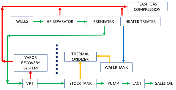
Figure 6 shows a typical unconventional light oil facility block diagram. Note the vapor recovery tank (VRT) and the dashed black break line. It separates the vapor recovery system from the tanks. The stock tanks have extremely low vapor rates, which reduces venting and increases revenue.
Figure 6. Typical unconventional surface facilities block diagram
Do you have a VRT in your design?
If you don’t you probably have vapor pressure issues and oxygen in the sales gas from the stock tanks and water tanks connected to the vapor recovery system.
The VRT operates at 1-5 psig (108-138 kPa) and is approximately 36” (1 m) in diameter and 35 (12 m) ft tall. The feed enters the top vapor space. This provides a pressure break from the stock tanks and prevents oxygen from entering your gas system. It also provides a final flash with no tank liquid head. If stock tanks are fed from the bottom, they will have 20 ft (7 m) (8.6 psig) (160 kPa) of liquid head which will add to the TVP if the tanks are not well mixed or the rates are high to prevent equilibrium.
It’s extremely important that the VRT is insulated and heated to ensure that this final flash occurs at more than 110 °F (43 °C) at the top of the tower and at 1-5 psig (108-138 kPa). Some designs use the hot exhaust gas from vapor recovery compressors to heat coils within the VRT. If you experience cold winters in West Texas or the Bakken, then make certain the VRT is heated, insulated, and close coupled to the heater treater. This also means that the stock tanks do not require insulation. The final critical flash has already taken place at the top of the heated VRT. The oil out of the VRT should also enter the top of the stock tank to ensure the last flash occurs at the lowest possible pressure. This can be accomplished via a small external cyclone whose outlet gas enters the top of the tank and whose liquid line enters the bottom of the tank. This liquid dip line ensures that no static electricity build up occurs with the liquid falling into the tank.
Some designs without VRT’s have approximately 200 ft (60 m)of distance between the heater treater and the stock tanks. In the winter the fluid from the treater cools on its way to the tanks and does not have an opportunity to have its final flash at 1 psig (108 kPa) and 110 °F (43 °C). If the tanks are uninsulated reflux condensation of propane and butane occurs further increasing the vapor pressure.
Another benefit of the VRT design is that gas will not be breaking out in the stock tanks causing venting. The tanks will be safer for your operating personnel to gauge.
The pressure break that the VRT provides also isolates the VRU system from pressure surges caused by fluctuating tank levels during loading / unloading.
Alternative Designs:
Here is something to consider if you have a field with 600 existing oil batteries and no VRT’s. Install a central condensate stabilizer for use in the winter. It requires double handling of the crude oil, but less CAPEX than modifying the existing batteries.
One Operator in West Texas is installing a Tankless Design using production separator clusters where production is sent to 3 phase separators where Oil, Gas, and Water are separated, metered, and sent via pipelines to Central Oil Treating and Stabilization Plants for final processing prior to sale. Eliminates Trucking, Increases Revenue by eliminating Flaring / Emission Control Devices from tanks.
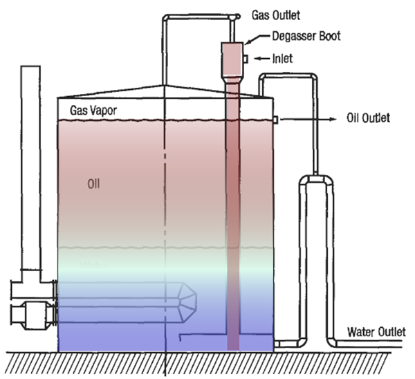
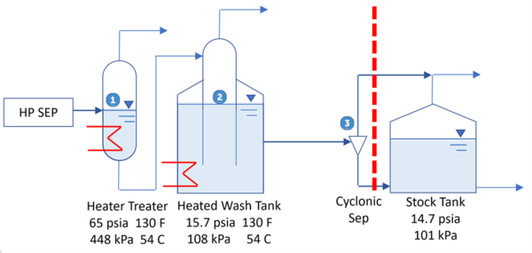
Another design to consider is a heated wash tank or gun barrel tank. It’s a combination of a VRT and a stock tank. Figure 7 presents an internally heated wash tank.
Figure 7. Internally heated wash tank
A Heated wash tank / gun barrel tank will have similar process performance to a VRT. Figure 9 presents a heated wash tank. The wash tank is not used to perform its normal oil / water dehydration performance, but to provide heat for the final flash at low pressure and to provide a liquid seal to prevent oxygen entering the system, reduce vapor recovery unit (VRU) horsepower, and eliminate the final flashing of gas and loss of revenue in the oil stock tanks. A summary of operation considerations is:
- Meets RVP / TVP at point # 2
- No oxygen into the gas system
- No stock tank vapor; 30% lower VRU power
- No tank venting; more revenue
- Tank head no impact to RVP/TVP
- Insulated treater & VRT – not entire battery
- No static electricity issues in top-fed tank
Figure 8. A heated wash tank can have similar performance to a VRT
Process Safety: Hot Oiling
Some operators use hot oil trucks to circulate their cold oil stock tanks to provide the heated flash in the winter. If the amount of propane and butane in the cold oil flash gas exceeds the limits of the thermal oxidizer, then it shuts down and the tanks will overpressure and vent locally. Venting of heavier than oil hydrocarbons particularly LPG is extremely dangerous and can lead to an unconfined vapor cloud explosion (UCVE). Hot oil trucks are direct fired and are an ignition source.
The following is an incident involving a hot oil truck at surface facility.
Posted on February 3, 2018 by Site Admin in News, Oilfield1 [4]:
HOBSON (Karnes County TX) – A worker continues to recover from burns after officials say he was injured when his truck caught fire at a tank battery off Farm-to-Market Road 81, which is operated by 1776 Energy Operators, LLC.
According to Texas Railroad Commission (RRC) spokesman Ramona Nye, the blaze erupted at about 4 p.m. Wednesday, Jan. 24, when a worker from Engineered Well Services drove up to service a crude oil tank. His truck burst into flames, igniting two tanks containing produced water and four that held crude oil.” [4]
Weather reports indicate a low of 43 °F (6 °C) the night before.
Some typical process safety issues to consider are listed below:
- Was the lease operator present?
- Was there a signed hot work permit?
- Was there a JSA?
- Do they monitor wind speed and direction?
- Do they shutdown other operations / trucking during this type of operation?
Summary:
To control vapor pressure light oil the following method / equipment can be used:
- Vapor recovery tower (VRT)
- Heated wash tank
- Condensate stabilizer
- Reduce tank levels
- Heat and insulate
For optimal operation, the following items should be considered:
- A heated gun barrel tank that is heated by an external furnace.
- Install a condensate stabilizer to maximize revenue and meet pipeline / trucking TVP specifications.
- Avoid infinite recycling of LPG by running your compressor discharge temperatures hot enough to prevent hydrocarbon liquid condensation and provide positive displacement pumps to continually move the condensed LPG into the sales gas line.
To learn more about similar cases and how to minimize operational problems, we suggest attending any of the following courses:
G4 (Gas Conditioning and Processing)
G5 (Advanced Applications in Gas Processing)
PF3 (Choosing the Right Facilities Equipment for the Reservoir)
PF4 (Oil Production and Processing Facilities)
PF49O (Troubleshooting Oil Processing Facilities)
PF49G (Troubleshooting Gas Processing Facilities)
PS4 (Process Safety Engineering)
By: James F Langer, P.E.
References:
- Langer, J., Infinite Recycle Impacts on Compression Systems, PetroSkills tip of the month, Aug 2017
- Zangeneh, B., “UNDERSTANDING RESERVOIR ENGINEERING ASPECTS OF SHALE OIL DEVELOPMENT ON THE ALASKA NORTH SLOPE,” M.S. Thesis, University of Alaska Fairbanks, May 2014.
- UniSim Design R443, Build 19153, Honeywell International Inc., 2017.
- https://oilfield1.com/2018/02/03/explosion-prayers-for-oilfield-worker-recovering-after-tanker-explosion-in-south-texas
Further Reading:
- Moshfeghian, M., Correlations for Conversion between True and Reid Vapor Pressures (TVP and RVP), PetroSkills tip of the month, Feb 2016
- Moshfeghian, M., Correlations for Vapor Pressure of Crude Oil Measured by Expansion Method (VPCRx), PetroSkills tip of the month, Nov 2017
- Conder, M W and Lawlor, K A; “Production and Processing, Production Characteristics of Liquids-Rich Resource Plays Challenge Facility Design,” American Oil and Gas Reporter- Editor’s Choice, May 2014.
- https://www.aogr.com/magazine/sneak-peek-preview/production-characteristics-of-liquids-rich-resource-plays-facility-design
- Conder, M W, and Schroer, A D; “Production Facility Design, Simulation Workflow Optimizes Facility Design for Producing Multiwell Pads,” American Oil and Gas Reporter- Editor’s Choice, May 2015.https://www.aogr.com/magazine/editors-choice/simulation-workflow-optimizes-facility-design-for-producing-multiwell-pads
- InterTek, http://www.intertek.com/ngl-condensate-boiling-video/), 2018
